COMPACtenna … COMPACT antenna
Easy to Install Easy to Use
VEHICLE & BASE STATION
7.5″ & 9″ VHF/UHF models
Models: 2M/440 2M/220/440 2M/440PLUS 220MAX LMR-I SCAN-III
Vehicle Application
Generally, best performance of a mobile antenna is achieved with location at the top of the vehicle.
Long antennas can be unsightly and often do not allow travel into garages, beneath underpasses,
and standard technology short antennas have significantly decreased performance and bandwidth.
COMPACtenna is LESS restrictive than most antennas which have only one optimum spot, being the center of the roof ONLY.
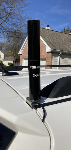
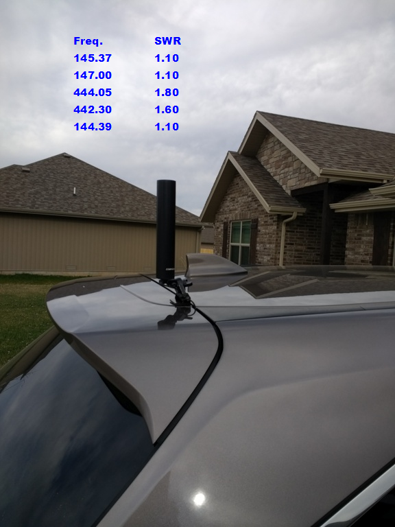
COMPACtenna 7.5″/9″ models have MULTIPLE optimum possible locations, the upper corners of the vehicle;
they are designed for best results (SWR, Performance) at an upper corner of a vehicle.
Tech.:
With a short antenna, the hot voltage point is quite close to the ground plane counterpoise with consequently low resistance.
The high inductance and capacitance of the COMPACtenna magnetic field resonator design
are balanced at the corners for proper overall impedance in a short antenna,
working in conjunction with the downward/sloping metal of the
vehicle at the corner locations having increased resistance effect.
And this geometric dimensional counterpoise also results in
a substantially omnidirectional VHF/UHF pattern.
METAL Ground Plane Vehicle Counterpoise
Apply antenna mount to metal with good (clean) ground connection
(magnet mount and often clamp types provide capacitive coupling to ground)
Vehicle Antenna Mount Types
Through-Hole mounts with vehicles with metal roofs have been found to work optimally more consistently than many other types.
One benefit is that they don’t have the challenge of adequate connection/coupling to ground plane counterpoise that some mount types may.
L-Bracket & Adjustable-Universal Bracket attached-to-vehicle-metal with screws type mounts are also favorites by many for similar reasons.
Magnet Mounts: As can be seen by the formulas, etc. below, magnet mount capacitive coupling is often quite good at VHF/UHF frequencies..
Lip Adjustable Mounts: See below.
If creating a hole/holes is/are being considered such as for a thru-hole mount or a bracket-with-screws type mount,
temporarily securing the mount, or trying a magnet mount (on steel, magnetically secured;
on aluminum, supported – capacitive coupling exists with both) or a clamp mount at/near the intended location,
with vehicle stationary and clear of surrounding metal, may help to give an idea of SWR before the hole(s) is/are made.
NMO Magnet Mount
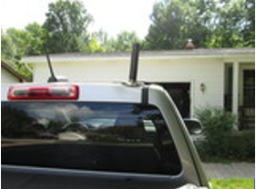
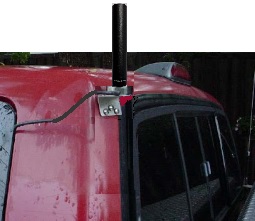
Magnet mount on corner of pickup truck cab:
Magnet Mounts
Capacitive Coupling Reactance
A magnet mount provides good coupling,
particularly at VHF/UHF, with little capacitive impedance:
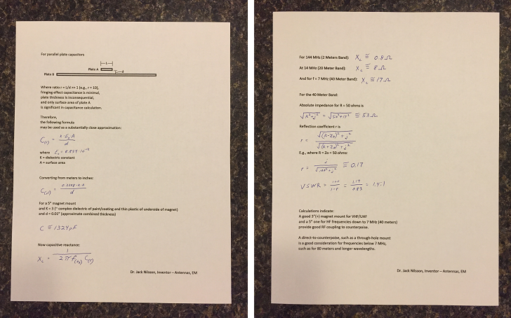
[Note that a magnet mount with a “thick” rubber bottom ‘boot’ will decrease capacitive coupling.]
For VHF/UHF, ‘flatter style’ magnet mounts often provide best SWR’s.
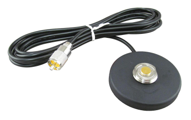
Examples of magnet mounts
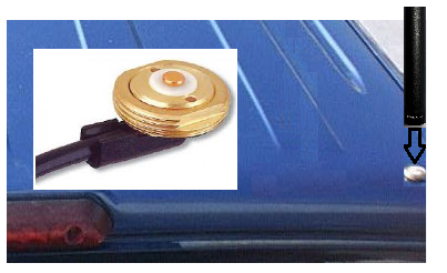
With these Pulse-Larsen magnet mount types, designed for up to microwave frequencies, leave the center pin/disk and inner dielectric in place:
NMO Magnet Mount at DX Engineering (solder type PL-259)
NMO Magnet Mount at Ham Radio Outlet (crimp type PL-259)
NMO Thru-Hole (Roof Type) Mount

Some NMO Thru-Hole Mounts require a 3/4″ hole, these require only a 3/8″ hole:
Diamond C213SNMO Mount at DX Engineering
Diamond C213SNMO Mount at Ham Radio Outlet
Hustler CHMA-P at Ham Radio Outlet
L-Bracket Body Mount Upper Corner Hatchback with NMO
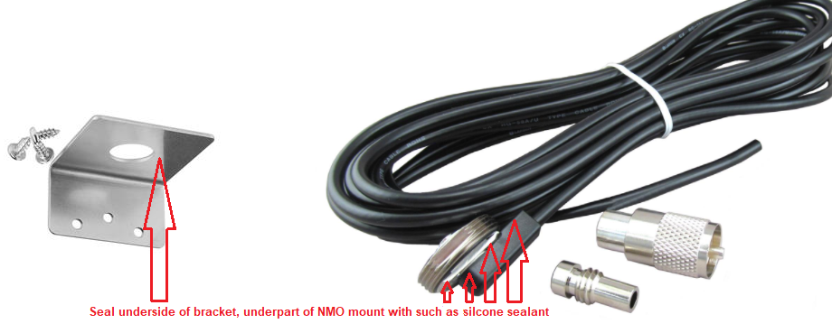

Example of NMO L-Bracket Mount Assembly
Larsen L-Bracket (3/4″ NMO hole) at DX Engineering
Larsen NMO Thru-Hole Mount with cable for 3/4″ hole at DX Engineering
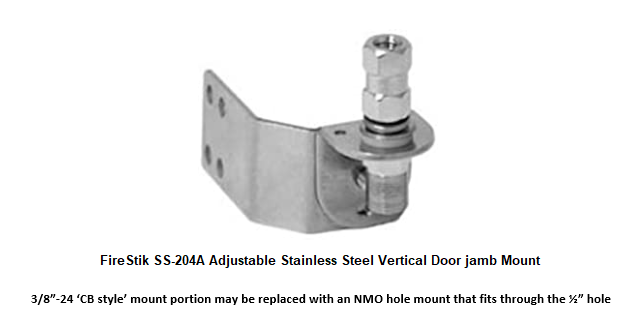
Adjustable-Universal bracket mount option
Can provide greater clearance and flexibility to achieve upper corner hatchback vehicle antenna mounting as above:
Below: A couple NMO through-hole mounts to consider for adjustable mount above
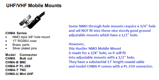
Hustler CHMA-P at Ham Radio Outlet
Many vehicles allow passage of small ~0.2″ diameter RG-58 coaxial cable as with the Hustler CHMA-P mount above,
but some vehicles have especially narrow gaps between the closed hatch/door.
The Diamond NMO mount below has 1/8″ diameter coaxial cable:
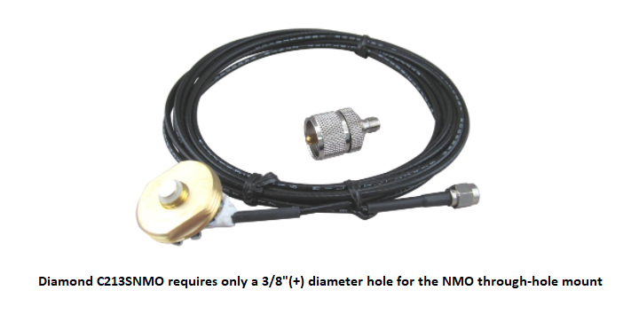
Diamond C213SNMO Mount at DX Engineering
Diamond C213SNMO Mount at Ham Radio Outlet
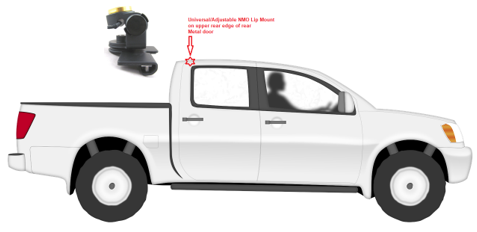
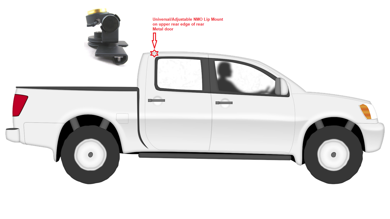
NMO Mobile Antenna Adjustable-Universal Lip Mounts
For SUV, Crossover and Van hatchback door upper corner
Also Pickup Truck upper rear of rear door
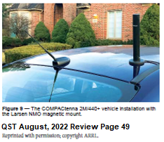
COMPACtenna 2M-220-440 W0RS Mobile Installation:
Example of NMO Mobile Antenna Adjustable-Universal Lip Mount
Diamond K412CNMO at DX Engineering
Diamond K412CNMO at Ham Radio Outlet
PICKUP TRUCKS
Magnet mount on corner of pickup truck cab:
Examples of magnet mounts
With these Pulse-Larsen magnet mount types, designed for up to microwave frequencies, leave the center pin/disk and inner dielectric in place:
NMO Magnet Mount at DX Engineering (solder type PL-259)
NMO Magnet Mount at Ham Radio Outlet (crimp type PL-259)
Example of NMO Mobile Antenna Adjustable-Universal Lip Mount
Diamond K412CNMO at DX Engineering
Diamond K412CNMO at Ham Radio Outlet
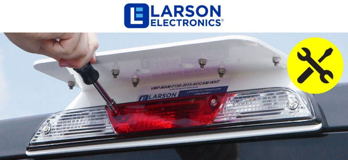
Users report success with installation of COMPACtenna on a plate-style 3rd brake light mount such as from LarsonElectronics.com at a corner of the plate away from the vehicle.
NMO Thru-Hole (Roof Type) Mount
Some NMO Thru-Hole Mounts require a 3/4″ hole, these require only a 3/8″ hole:
Diamond C213SNMO Mount at DX Engineering
Diamond C213SNMO Mount at Ham Radio Outlet
Hustler CHMA-P at Ham Radio Outlet
L-bracket on the upper back corners of the cab of pickup trucks.
Examples of NMO L-Bracket Mount Assemblies
Larsen L-Bracket (3/4″ NMO hole) at DX Engineering
Larsen NMO Thru-Hole Mount with cable for 3/4″ hole at DX Engineering
COMPACtenna customer comment on an LCARA Ham Radio YouTube Video about the COMPACtenna (V/U model) even outlasting his magnet mount! :
…The COMPACtenna….is a “go-to” for my BTECH UV-5×3 tri-band and works well with my Kenwood TM-V71A as well.
My mag mount -failed- after about 2-3 years of use… The COMPACtenna Antenna (did not fail) is my absolute FAVE antenna for VHF/UHF! 73!
This product provides enduring performance with proper installation, application, normal usage/conditions.
If there is a concern, check what you did/didn’t do in adhering to all.
7.5″ & 9″ VHF/UHF models
Models: 2M/440 2M/220/440 2M/440PLUS 220MAX LMR-I SCAN-III
Base Station Application
On COMPACtenna CompacCounterpoise Ground Plane Radial Base Station Adapter Kit:

To reduce parasitic interaction, min. recommended height above ground and distance from RF-interacting materials is 10’; performance often escalates substantially 30’ (+) above ground.
This product provides enduring performance with proper installation, application, normal usage/conditions.
If there is a concern, check what you did/didn’t do in adhering to all.
– – – – – – – – –
Models: PERFECT CB and PERFECT 10

COMPACtenna Antenna Models PERFECT 10 & PERFECT CB are the same,
except that the stinger whips are pre-cut for user convenience
to 44 ½” for the PERFECT CB, 40 ½” for the PERFECT 10.
[Installation notes apply to both models.]
Vehicle application: Mount on vehicle at a sensible location appropriately.
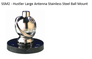
A variety of 3/8”-24 thread sturdy mount types are available on the market. See below.
SWR frequency range varies with vehicle construct, and where on the vehicle the antenna is mounted.
Keep antenna substantially above nearby metal, limit horizontally adjacent near field parasitic interaction.
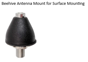
Base Station application: Mount antenna on a sufficient appropriate ground plane counterpoise.
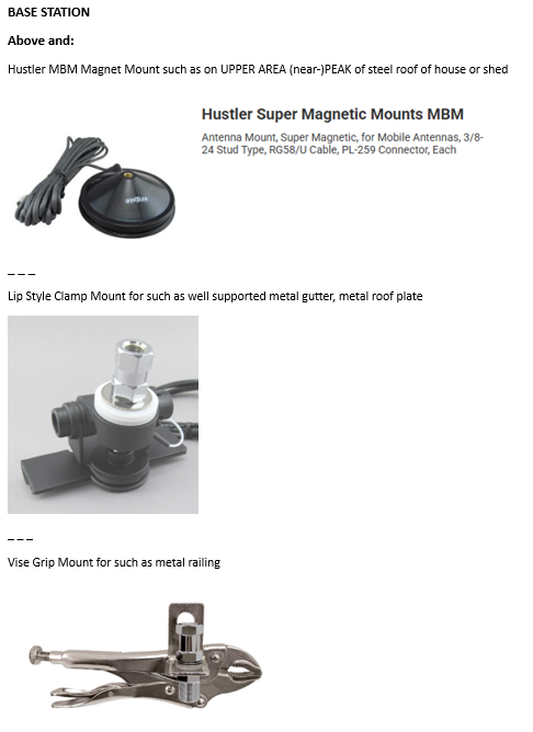
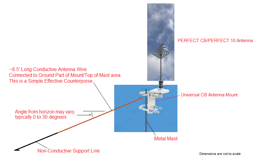
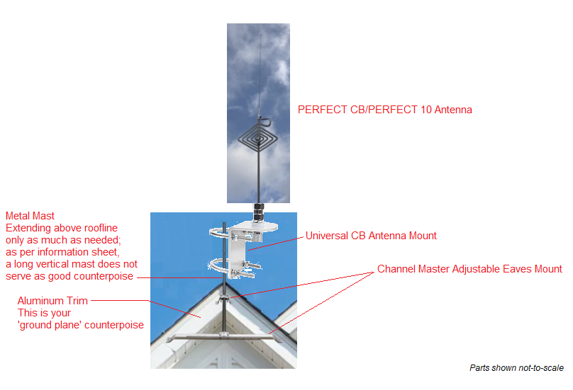
Possible installations include 3/8”-24 thread magnet/clamp/bracket mounts on house/shed/building metal roofs (upper area), well supported metal gutter/trim, a metal railing. A general rule is that expansive [8’(+)] metal in at least one horizontal/angled somewhat downward direction can yield a reasonable SWR. Mounting simply to the top of a vertical metal mast typically does not, although adding an ~8.5 foot long counterpoise wire connected at the top shield/ground side and supported horizontally/at a slight downward angle can serve as a simple effective counterpoise. See below.
Height above ground affects signal pattern, and SWR.
Keep antenna substantially above nearby metal/RF-interactive materials. Limit horizontally adjacent near field parasitic interaction, far field shadowing.
Outside installation is recommended to decrease noise from indoor switching power supplies and other electrical devices.
If creating a hole/holes is/are being considered, temporarily securing the mount (for vehicle application, not moving), or trying a magnet mount (on steel, magnetically secured; on aluminum, supported – capacitive coupling exists with both) or a clamp mount at/near the intended location, may help to give an idea of SWR before the hole(s) is/are made.
Always check SWR; operate only per transmitter specifications.
Tuning can be done by adjusting whip position in Ferrule, or trimming whip.
The frequency shifts ~0.1 MHz with ½” change in length; increase in length lowers freq.; decrease in length raises freq.
Use threadlocker on whip set screws after tuning is completed.
(V)SWR: Nominal < 2:1 [ Often 1.1-1.5:1 ]
Models PERFECT 10 & PERFECT CB are the same, except that the stinger whips are pre-cut for user convenience to 44 ½” for the PERFECT CB, 40 ½” for the PERFECT 10. The accessory ‘PERFECT 10/CB REPLACEMENT WHIP’ is 44 ½” long; trim if/as needed.
Wt. 1.5 lb.
Gain: Nominal 7(+) dB-MEG – Mean Effective Gain in the dynamic obstructed environments
of the world we live in, with COMPACtenna’s ‘PERFECT CB/PERFECT 10’ diverse EM (ElectroMagnetic) fields – phase diversity in same and orthogonal polarizations-elliptical polarization
Maximum Power Ratings – under normal use and conditions
1500 Watts SSB voice; 750 Watts FM-Digital voice; 500 Watts AM voice; 250 Watts Digital Data modes
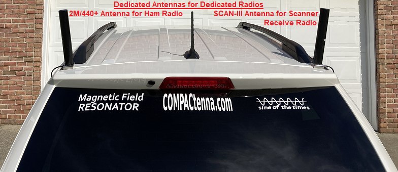
Each Antenna is quality checked and tuned. Keep antenna and mount contacts – area clean.
Removing, re-attaching antenna(s) repeatedly is not recommended as a general rule;
dedicated vehicle & base station systems are best.
[Design and specifications subject to change without notice.]
Considerations for sturdy mounting
Be prudent, showing care and conscientiousness


Paul from Texas sent a photo of his easy installation and writes:
I simply affixed the L-bracket of a standard mobile CB antenna mirror mount
on the end of my roof gutter with a standard vice grip.
This is the stealthy look and performance that I was looking for.
It’s working great!
SWR’s are 1:1 to 1:4 across 11 meters.
With my antenna mount on the gutter only about 10 feet above the ground,
I am talking with area locals 45+ miles away!
And I’ve been able to do DX as well all over the country.
Thank you!

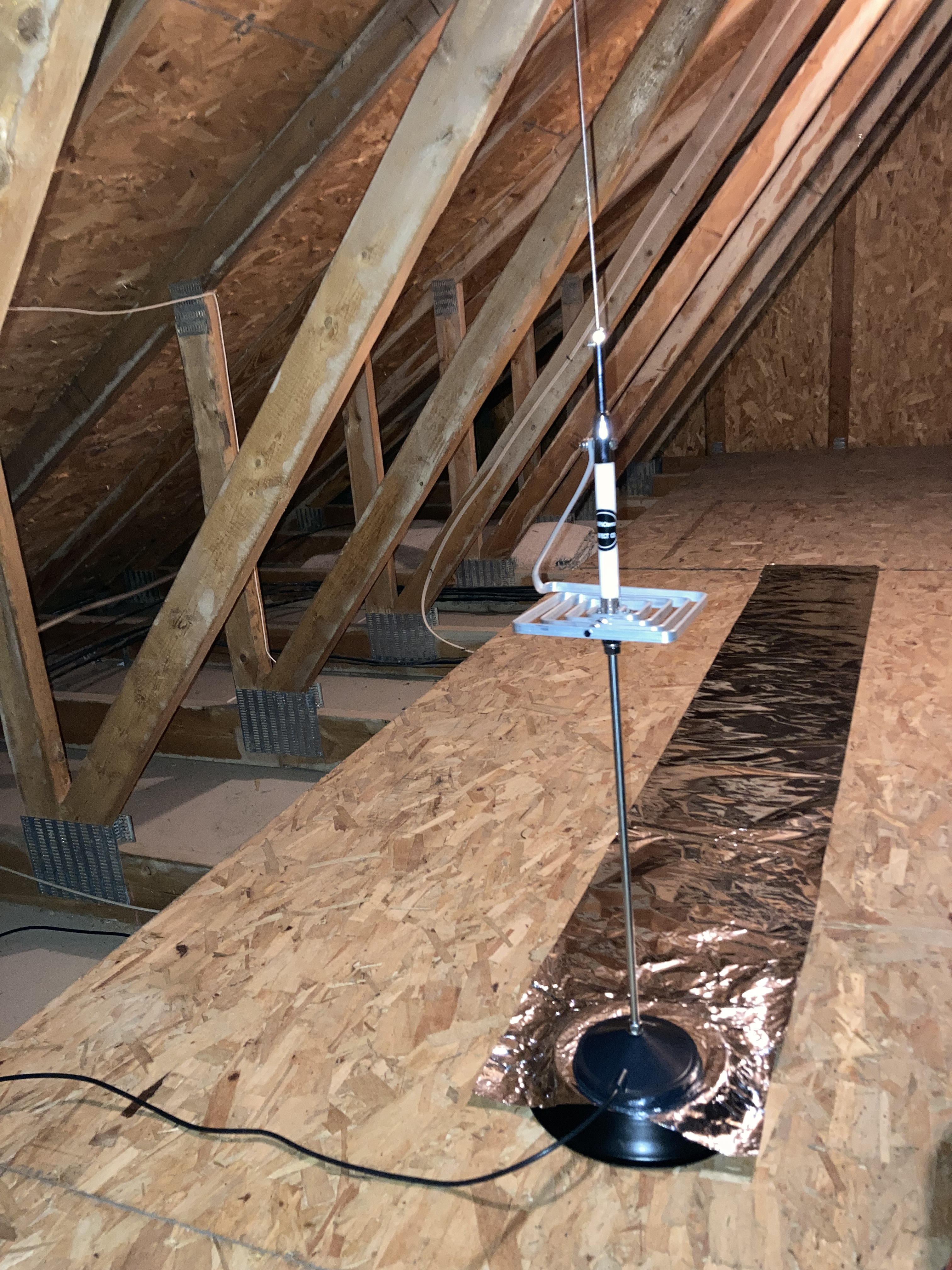
Although outdoor installation is recommended to reduce RF noise from indoor switching power supplies, etc., users report success with installations such as in this photo where about 8′ of standard aluminum foil is at its end sandwiched between a (Hustler brand) magnet mount above and a steel plate/cookie sheet/pan below:
This product provides enduring performance with proper installation, application, normal usage/conditions.
If there is a concern, check what you did/didn’t do in adhering to all.
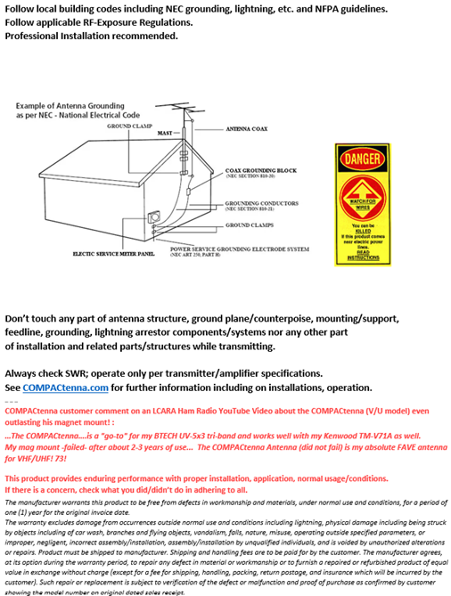
Follow local building codes including NEC grounding/lightning/etc. and NFPA guidelines.
Follow applicable RF-Exposure Regulations.
Professional Installation is recommended.
Don’t touch any part of antenna structure, ground plane/counterpoise, mounting/support, feedline, grounding,
lightning arrestor components/systems nor any other part of installation and related parts/structures while transmitting.
Optimizing Installation of small antennas …in ‘small spaces’
Here are some techniques that can help achieve the successes so many have.
Each situation is different.
Often the installation-to-operation is rather straightforward.
Some experimentation/optimizing can prove quite beneficial for your particular system; see below.
BAD CONNECTION – COMMON PROBLEM
One of the most common problems in any radio-antenna system is a connection problem.
A magnet mount may not have good continuity (internal disconnect); some are reported to be more reliable.
Connectors and adapters can be bad.
Some PL-259’s do not mate well with SO-239’s including at the transmitter, receiver, amplifier, test equipment.
Check your system as needed.
Limiting the number of connections is a good policy.
COMPACtenna Science & Technology – NMO 7.5″/9″ ANTENNA MODELS ARE DESIRABLY PRE-TUNED
With other ‘small’ antenna technologies it is ‘standard’ that one needs to tune the antenna structure itself,
sometimes changing the structural tuning for each frequency change.
With COMPACtenna Science & Technology, there is desirably no tuning of the antenna itself.
Instead, antenna system ‘positional tuning’ is only when necessary and accomplished essentially by changing the location
of the antenna/antenna+counterpoise system.
Examples:
Mobile: Moving the top-corner-of-vehicle-location NMO mount antenna even closer to the corner (as appropriate) on the vehicle
to an even better SWR-matched position.
Base Station: Moving a VHF/UHF antenna on CompacCounterpoise in an attic when there is interaction with nearby metal structures.
This is typically needed only when substantial parasitic interaction is ‘near’/influencing the antenna/counterpoise structure.
RF NOISE – DEVICES IN THE HOME
Receive performance can be very negatively affected in noisy RF environments…
Due to unintentional radiators
such as switching power supplies including in transformers commonly used for powering and charging many types of electronic equipment –
examples are for cell phones, laptops, TV’s, DVD players, etc.,
even within common household LED light bulbs;
computers, including as part of vehicles;
radio receivers which often use an intermediate frequency which is detectable outside the radio;
motors; dimmers; and corona from electrical powerlines.
And due to intentional radiators
such as wireless garage door openers, wireless microphones, RF universal remote control devices,
cordless telephones, wireless alarm systems, Wi-Fi transmitters, and Bluetooth radio devices.
Wi-Fi Routers are a common substantial problem.
These can all generate RF noise.
Especially in radios-receivers with lesser shielding and filtering including on the power line as well as on the RF input.
Front end overload and intermodulation problems can occur.
Sometimes the RF ‘noise’ is seen on the radio’s signal strength meter, yet sometimes it isn’t seen nor heard!
But it may be there nonetheless, causing desensitization of the receiver with poor reception of desired stations!
Some radios are considerably more ‘immune’ to RF noise that can occur in vehicles even with the vehicle off !
Of benefit can be toroids/RF beads on wires, cables and power leads at computers and electronic equipment and switching
power supplies and lamps because they can act as transmitting antennas.
A toroid/RF ferrite beads on a power strip cord help reduce RF from connected switching power supplies getting to electrical
wires of your house that can act as substantial antennas.
Wi-Fi ROUTERS !
Not only the switching power supply of the Wi-Fi router can cause RF noise, but
OFTEN THE WIFI ROUTER ITSELF CREATES SPURIOUS EMISSIONS!
AND SIMPLY APPLYING SEVERAL CLAMP-ON RF FERRITE BEADS ON THE POWER WIRE AT THE ROUTER
IS VERY EFFECTIVE; adding ferrite beads to the ethernet cable at the router can provide some additional noise reduction.
It is not uncommon to see a substantial noise level on the radio’s signal meter,
and for S-meter reading to drop to zero by simply applying the ferrite beads as above.
SEPARATING ANTENNA & RADIO FROM INTERFERING ELECTRONICS
Having the ANTENNA OUTSIDE often substantially reduces RF noise in that much of it commonly originates from within the house.
But simply creating a separation can be productive.
Distancing of the antenna from the computer and electronics for best reception is often a matter of experimentation.
Try different places at different distances.
(One ‘rule of thumb’ is 15 feet or more away.)
RF NOISE – HAM/SHORTWAVE/SCANNER RADIO SWITCHING POWER SUPPLY
In addition, switching power supplies used to power the HAM Radio
can be very detrimental to BOTH TRANSMIT AND RECEIVE.
The RF ‘noise’ from these switching power supplies can understandably affect receive,
but also create oscillations that affect things such as transmit audio,
and even SWR measurement and tuner circuits!
Some have better filtering, but many operators recommend
non-switching transformer types especially for HF/SW transceivers/receivers
and even for (especially non-FM such as SSB) VHF/UHF transceivers/receivers.
RF ferrite beads/toroids on power leads at the power supply can be helpful.
RF FROM THE ANTENNA TO THE HAM RADIO – SMALL SPACES
RF from the antenna itself through the air with proximity to the radio/equipment
can cause similar problems.
Increasing distance from the antenna to the equipment can be very helpful, and decreases RF exposure.
Garage Door Openers
Avoid proximity to automatic garage door openers;
activation can occur.
GROUNDING
A good System Ground is important.
Stray RF can be substantially reduced.
Along with using the same power circuit/outlet as appropriate for your station equipment,
ground loop problems such as noise in reception can be dramatically reduced by a good common ground.
A poor RF ground can result in weak signals due to ground wire losses.
RF feedback can cause such things as modulation distortion or even stop your radio from working.
RF FERRITE BEADS/TOROIDS ON ALL WIRES (TO/) AT THE RADIO CAN (ALSO) BE QUITE ADVANTAGEOUS,
such as Power, Microphone, Speaker, Amplifier, Data, PC, and Accessory Leads/Wires/Cables.
Transmitter Protection:
Check SWR with an antenna analyzer.
Modify your installation for improvement if needed.
Reduce power output as appropriate.