compact ANTENNAS
small Powerful Antennas for
Ham Radio LMR – Land Mobile Radio (Govt, Business, Marine, GMRS) Scanner
Patented Technology – Quality Machining & Skillfully Hand-Crafted
Each Antenna manufactured is Precisely Tested/Tuned before shipment.
MADE IN THE USA
Product Listing follows some beneficial information
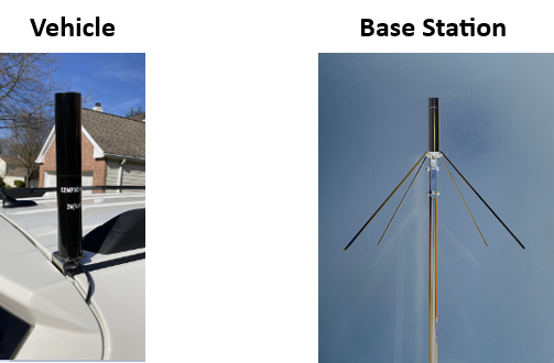
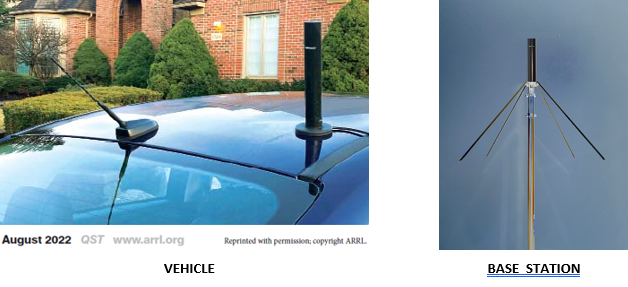
Generally, best performance of a mobile antenna is achieved with location at the top of the vehicle.
Long antennas can be unsightly and often do not allow travel into garages, beneath underpasses,
and standard technology short antennas have significantly decreased performance and bandwidth.
The short yet powerful COMPACtenna is designed for best results (SWR, Performance) at an upper corner of a vehicle.


QST (ARRL) August, 2022: 

“This COMPACtenna Invention by Dr. Jack Nilsson is the first real new development in antenna communication design since Marconi/Tesla,
a paradigm shift in thinking that works amazingly well.”
Dr. Marcus Durham, PhD Electronics Engineering, Life Fellow IEEE
NMOD, Amateur Extra
“…consistently strong signal …while he drove all the way to Rancho Santa Margarita, through areas that would otherwise produce marginal signals with a more common antenna. …
Resulting diverse effective electromagnetic fields are claimed to mitigate signal drops, reduce flutter, and increase reliable range, which Randy has confirmed.”
Newsletter Article – COMPACtenna Study – County of Orange, CA Radio Amateur Civil Emergency Service
Appreciation: County of Orange, CA Radio Amateur Civil Emergency Service – Ken Bourne, W6HK, OCRACES Chief Radio Officer, Randy Benicky, N6PRL
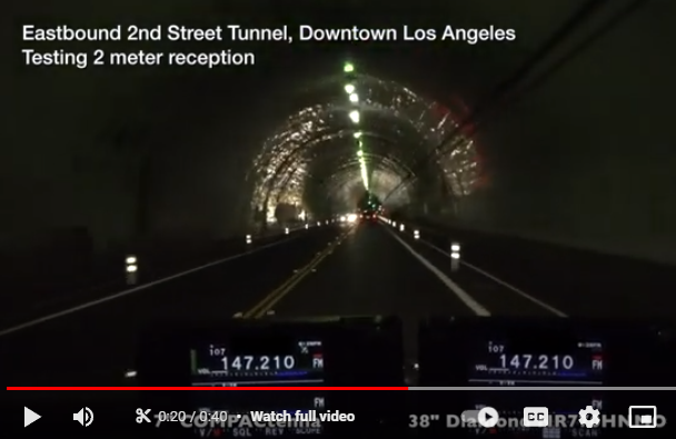
RECEIVE Test – COMPACtenna Reduces Flutter Even in Underground Tunnels – a 1 minute YouTube Shorts
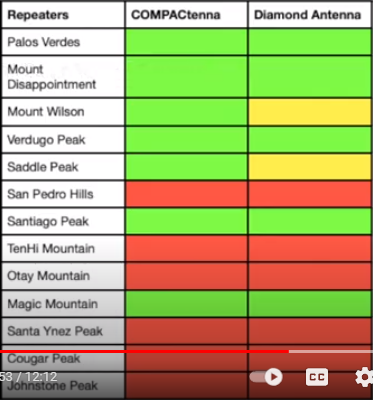
COMPACtenna Science & Technology increases the number of usable regional repeaters (and simplex stations) in common environments.
This is due to its Non-Line-Of-Sight capabilities.
The benefit applies to COMPACtenna on vehicles, as well as COMPACtenna with the CompacCounterpoise for base stations.
TRANSMIT TEST – 12 Minute YouTube Video
The 2018 Dayton International Hamvention – New product Showcase 5 minute Presentation, YouTube Link
COMPACtenna Quanta – Near & Far Fields – 1 Hr. Talk, then 20 minute Q&A – Conejo Valley (CA) Amateur Radio Club 1.20.22 – YouTube Link
Patented COMPACtenna Revolutionary Design – small yet Powerful
With a special design construct of spiraled and cylindrical metal sheeting including ‘extended flat monofilar spiral Tesla-like coils’,
all resistance, inductance and capacitance (matching) is efficiently done by the physical metallic geometric form of the antenna itself,
as opposed to internal or external (lossy) components of other designs.
“Magnetic Field Resonator”: This built-in resonating matching system is an effectual component of the electromagnetic E & H fields
production, resulting in better performance than expected for such a small antenna.
With a particularly strong magnetic near field, proximity noise is reduced.
And resulting diverse effective electromagnetic fields (elliptical polarization and phase diversity) as well as broad elevation coordinate
signal pattern provides stabilized signals in our common Non-Line of Sight environments, with temperature and humidity inversion
pathways & tropospheric propagation, and satellite communications, further enhancing performance
in our world of (dynamic) obstructions, mitigating signal drops, reducing flutter, and increasing reliable range.
And the 9″ Models of COMPACtenna Dominate long standard technology antennas even in Line-Of-Sight Long Range Communications.
KK4SBS
7.5″ model 2M/220/440
Not sure what sort of … magic wizardry you’ve pulled off here but the performance of the 70cm/1.25m/2m tri-band
COMPACtenna is absolutely phenomenal!
The performance on all three bands, right out of the box, has been nothing short of incredible.
I had been running a B-10NMO (70cm/2m & 12″ tall).
Since switching to the COMPACtenna, I am now receiving reports of full quieting on repeaters that I previously struggled to even Rx at ~S5.
I’m now able to Rx those same machines at S8-S9+ with no issues and to my shock with no trouble on Rx/Tx in the areas I used to struggle.
So thank you for engineering such an awesome product. …

YouTube Link to Testing & Analysis of COMPACtenna versus ‘Standard Technology Antennas’ by Josh Nash of Ham Radio Crash Course
from eHam.net:

N3JHU – VHF/UHF Long Range Enthusiast
[below from QRZ.com public info.]
124 MILES !

ELECTRIC VEHICLES [Also Electronic Components of Gas-Powered Vehicles]
RF noise (EMI) that can be generated by increasingly popular electric vehicles can lead to problems (EMC) with receivers and transceivers.
The COMPACtenna with its beneficial balance of substantial electric and magnetic components in the Near Field
(and field-photon synergistic harmonious summation resulting in a powerful EM Far Field)
has the potential to mitigate such interference.
Danny Harber, KI5EXY, active in the Montgomery County, Texas area FEMA, Search & Rescue, and ARES communications found this
to be another important benefit of COMPACtenna:
On my Tesla vehicle, I have been testing various antennas including long high gain VHF/UHF ones.
There is a noise problem when driving as well as when parked in the ‘On’ mode,
even with the repeater only 8 miles from my location.
The COMPACtenna does not have that issue.
SATELLITE COMMUNICATIONS
With hemispheric signal pattern and elliptical polarization, this novel technology is also an excellent, easy to use satellite communications antenna.
QST August 2022 (ARRL):
Satellite operation was one of the other use cases
suggested in the instructions. While using the radio in
my car, I tried a couple of FM satellite passes with the
new ISS repeater and SO-50. On both occasions I was
able to get into the satellites and make a couple of
contacts.
Brad Smith, KC9UQR – Summary of Comments:
I use the COMPACtenna.
It is elliptically polarized …and is also very good at high elevations/working directly overhead.
…there is no “doughnut hole”.
It is a very good satellite antenna.
It does work better than a vertical.
I have tried many antennas, including 1/4, 1/2, and 5/8 wave verticals and an eggbeater.
I am very impressed by this little antenna.
The proof is when you get out into the field and make a contact and I am doing that every day.
Satellite Contact by Eric Hofer, KJ4YZI – Ham Radio Concepts YouTube Link
LAND MOBILE RADIO – Government & Commercial Communications
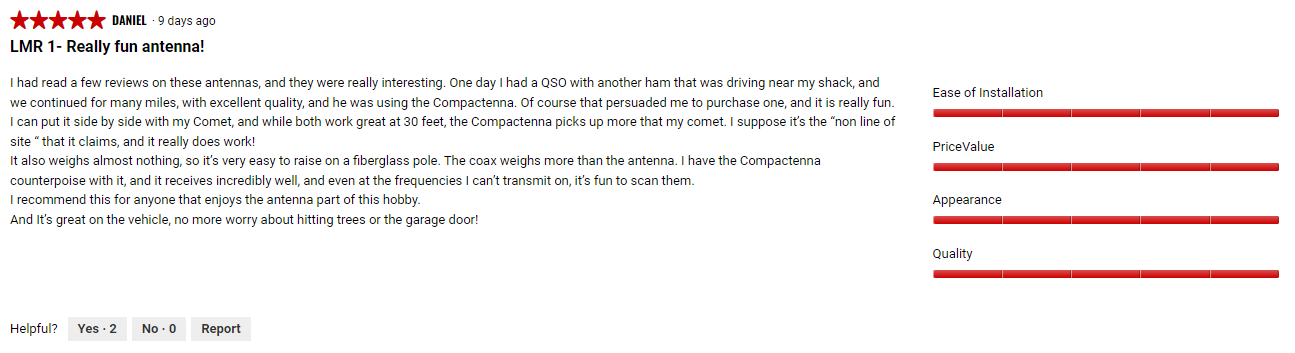
COMPACtenna: model LMR-I
[below from eHam.net]

AF1UD reports on the LMR-I:
I really like it.
I get the same performance that I got out of the Comet CA-2X4SR in 1/4 of the size!
The big thing is that in my area I would always lose VHF reception going down this main road… I no longer lose reception!
SCANNER RADIO
COMPACtenna: model SCAN-III
[below from eHam.net]

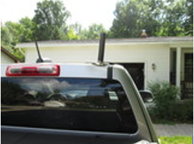
PICKUP TRUCKS
[See INSTALLS Page for Pickup Truck mounting considerations.]

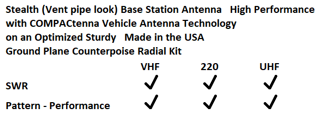
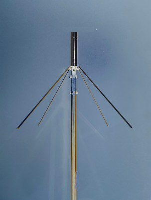
BASE STATION
Create a powerful yet small Base Station Antenna, using the CompacCounterpoise Optimized Base Station Ground Plane paired with a COMPACtenna Mobile Antenna.
Fits almost anywhere, and stealthy.

This Ground Plane Radials System is designed to work well at all bands in its specified frequency range.
The designated band(s) of the antenna mounted to it determines the end-results.
Models:
CompacCounterpoise (UHF-Female/SO-239 conn. for PL-259/UHF-Male terminated Coaxial Lead – 144-512 MHz)
CompacCounterpoise-N (N-Female conn. for N-Male terminated Coaxial Lead – 144-1000 MHz)
Base Station COMPACtenna on CompacCounterpoise DEMO by Eric Hofer, KJ4YZI – Ham Radio Concepts YouTube Link
John & Eileen Whitesell of Oklahoma were using a J-Pole antenna on their porch, but had a high noise floor.
They switched to the COMPACtenna model 2M/440+ on CompacCounterpoise Ground Plane Radial Kit.
The unwanted RF noise went away, and they had much better desired signal even with forest penetration.

Jim Mac from NM Experiences with COMPACtenna Technology
With SDRplay RSPdx
Heard a repeater on 2 meters from Mount Lemon to Las Cruces 200 miles
The Caballo mountain range is around 6500 ft.
GMRS
Really good results.
I can hit a repeater using 5 watts that is about 50 miles away.
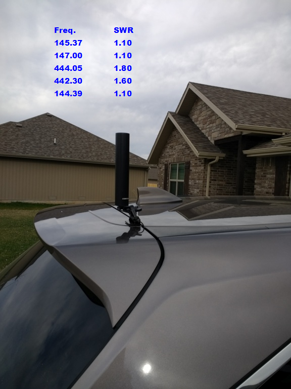
SWR
I am getting SWR’s of 1.2-1.6
I find all this this hard to believe, but can’t dispute the data.
Excellent, durable antenna.
Reviews of CompacCounterpoise (Base Station Ground Plane for VHF/UHF NMO Mobile Antennas) on DX Engineering:

COMPACtenna HF


COMPACtenna 20/40Micro
“REVOLUTIONARY” – only 10” x 10” x 10”
HF ‘Plug-and-Play’ Connect to your radio/coaxial lead & operate in seconds
A user of the new COMPACtenna model 20/40Micro, successfully having two-way communications
with SSB voice on the 20 meter and 40 meter bands around the USA and Canada, plus NVIS says:
“Painting the airwaves with the NEW COMPACtenna 20/40Micro,
it’s like you shouldn’t be able to do this but, You Can!
It seems to defy physics as we understand it.”
Fun in the snow outside Lorain County Community College
at the NOARS (Northern Ohio Amateur Radio Society) 2024 Winter Hamfest
with Dave, KD8MXE a great guy, and the New 20/40Micro: 14 seconds long YouTube Link
COMPACtenna 20/40 Micro, HOA Stealth Antenna, On-Air Testing And Complete Review – Ham Radio Concepts – 26 minute Video YouTube Link
Dr. Jack Nilsson – Model 20/40Micro – COMPACtenna Revolutionary tiny HF Antenna – 14 minute Video – YouTube Link
[ Referenced at end of video above:
COMPACtenna Quanta – Near & Far Fields – 1 Hr. Talk, then 20 minute Q&A – Conejo Valley (CA) Amateur Radio Club 1.20.22 – YouTube Link ]
– – –
Synopsis of: My Impressions of the COMPACtenna 20/40Micro HF Antenna by Tom, N8FDY [ Full review below ]
So, I had a chance to test out this light and small antenna that works on 40 meters and 20 meters.
Those happen to be the two bands I was interested in using on these outings with Elaine.


On Easter Sunday we put up the antenna and I started to listen around the bands.
The noise level seemed lower than I’m used to with other antennas.
I set my radio to transmit only 15 watts per the instructions for the
10 inch COMPACtenna 20/40 Micro HF antenna.
You can use up to 100 watts on SSB, but for all other modes it is a maximum of 15 watts.
I was a little skeptical because my current antennas are a
24 FEET Tall Hustler 6BTV with multiple ground radials and a
65 FEET Long 40m EFHW.
I needed at least 30 watts to talk to anyone on FT8 with my current antennas and a lot more power for DX.
I started testing the COMPACtenna 20/40Micro on 20 meters.
My first contact was Teddy, WA4TED in McMinnville, TN, 444.6 miles away,
which is good for 15 watts.
My next contact was Terry, KE0RB in Marion, IA, even farther away at 500.4 miles.
My next contact was Jeffery, KC5TT in Katy, TX, which is 1115.3 miles away.
I decided to switch to 40m to see how the NVIS part of the antenna works.
My first contact on 40m was James, WA4YWM in Quakertown, PA, 349.2 miles away.
My next contact was Richard, KF9KV in New Glarus, WI, 406.5 miles away.
After that it was Wayne, AC9HP in Indianapolis, IN, 256.9 miles away, good for NVIS.
Now back to 20m. I contacted Roger, KO4O in Trinity, AL, at 546.9 miles.
I thought I was doing pretty well for 15-watt DX,
since these contacts beat my current large antennas at that power level !
And then this happened…
My last contact was Luis, EA1A in Cantabria Spain,
That’s 3,821.3 miles away!

COMPACtenna – NO tuning (of antenna structure)
Vehicle – 7.5″, 9″ models
Often allowing passage into garages, drive-thru and below overhangs and branches
Home
For HOA’s, condo’s, apartments, homes
Examples: 7.5″, 9″ models on CompacCounterpoise for attic; inconspicuous (“stealth”) roof installation; on backyard mast/pole
20/40Micro in attic; inconspicuous in backyard on wood/fiberglass archway-arbor-trellis, pergola
Parks (POTA), Camp Grounds, Field Emergency Deployment
[Follow local building codes including NEC grounding/lightning/etc. and NFPA guidelines.]
[Follow applicable RF-Exposure Regulations.]
[Professional Installation recommended.]
PRODUCTS
Click on model of interest, or scroll down to view all models and valuable information.
Ham Radio
2 Meters/220/440 (only 7.5″)
2 Meters/440 (only 7.5″) (when 220 band isn’t needed – lower price)
2 Meters/440 + (Added Gain) (9″)
220 MAX (220MHz Band ONLY but Higher Gain) (9″)
Land Mobile Radio
Govt, Business, Marine, GMRS
Two Way Radio (Transmit & Receive)
LMR-I (9″)
Scanner Radio
Antenna for Scanner Receive Radios
SCAN-III (9″)
“Ultimate” VHF/UHF Ground Plane Radial Kit
For NMO Mobile Antennas
CompacCounterpoise & CompacCounterpoise-N
“REVOLUTIONARY” tiny HF Antenna
20 & 40 Meter Bands – only 10″ size
Model 20/40Micro
Model SCAN-III
Scanner Radio Antenna for NMO mounts
Broad elevation coordinate signal pattern and elliptical polarization of COMPACtenna provides stabilized signals in our common Non Line of Sight environments,
with temperature and humidity inversion pathways as well as tropospheric propagation, and satellite communications.
Product Name: COMPACtenna MADE IN THE USA Model: SCAN-III 9”
SCAN-III Compact High Performance SCANNER RADIO Antenna 100 – 1500 MHz
Including:
I. Civilian – VHF & UHF Air bands, Amateur Radio, Weather Channels, etc.
II. Commercial – Trucking, Dispatch, Railroad, Aeronautical, etc.
III. Government – Public Service-Safety/Local, State, Federal Govt/Military Frequency Bands
Police, Fire, Sheriff, Emergency Medical,
State Highway Patrol, Homeland Security, U.S. Federal, Military, Marine, Aircraft, etc.
Digital & Analog
Land Based and Satellite Communications
Antenna Type: Unique Electric/Magnetic Field Diversity Science & Technology Patented Design Patent No. US 9,407,001
With a special design construct of spiraled and cylindrical metal sheeting including ‘extended flat monofilar spiral Tesla-like coils’,
all resistance, inductance and capacitance (matching) is efficiently done by the physical metallic geometric form of the antenna itself,
as opposed to internal or external (lossy) components of other designs.
“Magnetic Field Resonator”: This built-in resonating matching system is an effectual component of the electromagnetic E & H fields production, resulting in better performance than expected for such a small antenna.
With a particularly strong magnetic near field, proximity noise is reduced.
And resulting diverse effective electromagnetic fields (elliptical polarization and phase diversity) as well as broad elevation coordinate signal pattern provides stabilized signals in our common Non-Line of Sight environments, with temperature and humidity inversion pathways & tropospheric propagation, and satellite communications, further enhancing performance in our world of (dynamic) obstructions, mitigating signal drops, reducing flutter, and increasing reliable range.
Reliable leaf spring style NMO connector on antenna for standard center-stud style NMO mounts
Best performance is generally seen when mounting at upper corners of a vehicle.
Signal pattern is substantially omnidirectional at corner locations, utilizing the downward/sloping metal of vehicle as counterpoise
METAL Ground Plane Vehicle Counterpoise – Apply antenna mount to metal with good (clean) ground connection;
Magnet mount type provides capacitive coupling, the ‘Flat’ style often provides best SWR’s
Mount types: see INSTALLS page
Only ~ 9” long x 1.5” dia.
Each antenna manufactured is precisely tested/tuned before shipment.
Gain: Nominal 5(+) dB-MEG
[Due to properties listed above, performance is greater than predicted based on gain alone
in NLOS (Non-Line-Of-Sight) environments which is the world we live in.]
Base Station antenna
The SCAN-III may also be used as a high performance 100-1500 MHz compact base station Scanner Radio antenna
by utilizing the COMPACtenna CompacCounterpoise, a heavy duty ground plane counterpoise radial kit
optimized for gain, pattern and SWR on VHF and UHF frequencies.
To reduce parasitic interaction, min. recommended height above ground and distance from RF-interacting materials is 10’; performance often escalates substantially 30’ (+) above ground.
Each Antenna is quality checked and tuned. Keep antenna and mount contacts clean. Fine grit emery cloth, for example, may remove oxidation. Thread lengths and center contact heights of different NMO mounts vary; make certain of good contact by antenna leaf spring – at times pulling the antenna leaf spring downward slightly is helpful before screwing antenna onto mount, especially if changing to another mount. Removing, re-attaching antenna repeatedly is not recommended; dedicated vehicle & base station systems are best. Use lube provided for NMO threads, center contacts and gasket, hand tighten securely. Brushless car washes, hand washing reduce risk of antenna/mounting damage. The antenna side screw is an added measure for secure physical integrity; it is to be left alone.
[Design and specifications subject to change without notice.]
[Above reviews from eHam.net]

 By Bob Grove, W8JHD “The prediction of signal flutter reduction was true as well;
when annoying flutter interrupted reception of weak signals on the whip,
reception was much smoother with the COMPACtenna.”
Increased Reliable Range in the dynamically obstructed NLOS (Non Line Of Sight) Environment we live in.
***
Mobile: For best performance, mount your COMPACtenna
at/near an upper corner of your vehicle.
See top of this Home Page and ‘INSTALLS’ page.
***
Available at:
Link to COMPACtenna model SCAN-III at DX Engineering
Link to COMPACtenna model SCAN-III at Ham Radio Outlet
Model 2M/220/440 Tri-Band
Ham Radio 2-Meter + 220 + 440 Bands for NMO mounts
Broad elevation coordinate signal pattern and elliptical polarization of COMPACtenna provides stabilized signals in our common Non Line of Sight environments,
with temperature and humidity inversion pathways as well as tropospheric propagation, and satellite communications.
Product Name: COMPACtenna MADE IN THE USA Model: 2M/220/440 7.5”
Optimized Compact High Performance HAM Radio Antenna for 2 Meter + 220 + 440 Bands
Only ~ 7.5” long x 1.5” dia.
Reliable leaf spring style NMO connector on antenna for standard center-stud style NMO mounts
Antenna Type: Unique Electric/Magnetic Field Diversity Science & Technology Patented Design Patent No. US 9,407,001
With a special design construct of spiraled and cylindrical metal sheeting including ‘extended flat monofilar spiral Tesla-like coils’,
all resistance, inductance and capacitance (matching) is efficiently done by the physical metallic geometric form of the antenna itself,
as opposed to internal or external (lossy) components of other designs.
“Magnetic Field Resonator”: This built-in resonating matching system is an effectual component of the electromagnetic E & H fields
production, resulting in better performance than expected for such a small antenna.
With a particularly strong magnetic near field, proximity noise is reduced.
And resulting diverse effective electromagnetic fields (elliptical polarization and phase diversity) as well as broad elevation coordinate
signal pattern provides stabilized signals in our common Non-Line of Sight environments, with temperature and humidity inversion
pathways & tropospheric propagation, and satellite communications, further enhancing performance
in our world of (dynamic) obstructions, mitigating signal drops, reducing flutter, and increasing reliable range.
Each antenna manufactured is precisely tested/tuned before shipment.
System Applications:
Digital & Analog VHF Amateur (HAM) Radio
Digital & Analog 220 Band Amateur (HAM) Radio
Digital & Analog UHF Amateur (HAM) Radio
Broad elevation coordinate signal pattern and elliptical polarization of COMPACtenna provides stabilized signals
in our common Non Line of Sight environments, with temperature and humidity inversion pathways
as well as tropospheric propagation, and SATELLITE communications.
Maximum Power Rating: 85 Watts 2 Meter Band; 30 watts 220 Band; 50 Watts 440 Band
At maximum power, duty cycle is 50%: Up to 1 minute transmit in any 2-minute period.
Under normal use and conditions
With longer transmissions, higher duty cycles, incl. with such as digital communications, decrease power, provide ‘cooling-off’ periods.
Gain: Nominal 3(+) dB-MEG
Due to diverse EM Fields of the Magnetic Field Resonator, performance is greater than predicted
based on (singular polarization/peak gain) field-range/anechoic chamber gain studies alone,
in NLOS (Non-Line-Of-Sight) environments which is the world we live in.
(V)SWR: Nominal < 2:1 144-148 MHz; 222-225 MHz; 430-450 MHz
Best (V)SWR’s especially on VHF frequencies are generally seen when mounting at upper corners of a vehicle.
Signal pattern is substantially omnidirectional at corner locations, utilizing the downward/sloping metal of vehicle as counterpoise
METAL Ground Plane Vehicle Counterpoise – Apply antenna mount to metal with good (clean) ground connection;
Magnet mount type provides capacitive coupling, the ‘Flat’ style often provides best SWR’s
Mount types: see INSTALLS page
(V)SWR’s can vary with size & shape of vehicle & accessories; (V)SWR’s seen by the radio are often lower due to feed-line attenuation.
Always check SWR; operate only per transmitter/amplifier specifications.
Base Station antenna
This revolutionary antenna may also be used as a high performance compact base station antenna
by utilizing the COMPACtenna CompacCounterpoise, a heavy duty ground plane counterpoise radial kit
optimized for gain, pattern and SWR on VHF and UHF frequencies. To reduce parasitic interaction, min. recommended height above ground and distance from RF-interacting materials is 10’; performance often escalates substantially 30’ (+) above ground.
Each Antenna is quality checked and tuned. Keep antenna and mount contacts clean. Fine grit emery cloth, for example, may remove oxidation. Thread lengths and center contact heights of different NMO mounts vary; make certain of good contact by antenna leaf spring – at times pulling the antenna leaf spring downward slightly is helpful before screwing antenna onto mount, especially if changing to another mount. Removing, re-attaching antenna repeatedly is not recommended; dedicated vehicle & base station systems are best. Use lube provided for NMO threads, center contacts and gasket, hand tighten securely. Brushless car washes, hand washing reduce risk of antenna/mounting damage. The antenna side screw is an added measure for secure physical integrity; it is to be left alone.
[Design and specifications subject to change without notice.]
Scott Roberts, KB3CBC submitted a very well written report:
For one specific case: there is a venerable major manufacturer whose antennas are used by first responders and amateur radio operators (me) for decades. The particular antenna by this manufacturer is used on 2/70 and gave me a benchmark to compare the CompacTenna side by side. In urban, NLOS environments, the CompacTenna beat the 2/70 antenna in every case.
With regards to the magnetic vs electric fields: a fast but inaccurate translation would be to say that this antenna functions as an omnidirectional circularly polarized antenna, and if you didn’t know any better, that’s what you would hear on the radio and see from your reception and transmission reports. It’s a lot more complicated than that and would recommend you review the various YouTube videos Dr. Jack put together to address this topic. Antenna analyzers and plots only give you part of the story, primarily based upon the E-field. It doesn’t show you, directly, what’s happening from the H-field side. Use a spectrum analyzer to compare received signals, though, and you’ll see the difference. The noise floor was reduced by approximately 3db and the signals were more evenly distributed. Signals that were close to the noise floor were observed to have increased by 3-6db, and stronger signals were slightly attenuated. The result is that there was minimal fading and the capability to hear signals that I could not using other manufacturer’s antennas.
Digital Communications – DMR Radio with COMPACtenna Science & Technology (eHam.net):

Thank you, Carlos.

6 Minute Video of Tom Medlin of W5KUB.com Interviewing Dr. Jack Nilsson Regarding 7″ COMPACtenna Model 2M/220/440
– – –
Testimonial:
Our company “Ham and HiFi” purchased a Compactenna 2M/220/440 antenna from HRO recently!
We use the antenna for testing radios we acquire from ” ham radio collections” we purchase from all over the US !
The construction of our shop / warehouse is with foil backed insulation, steel doors and steel roof
which have made using inside antennas a problem …..
But when using the Compactenna I’m now able to connect to repeaters through out the Reno / Sparks area!
Easy to install, easy to use ( no tuning ), wide banded and will handle 85 watts on 2, 50 watts on 220 / 440 !
Best of all a small footprint and it works ! I ordered another for my truck !
Regards, Don W7SSB
HAMandHiFi.com
COMPACtenna Science & Technology – Superior Earth Communications (Land Mobile), Satellite, etc.:
Satellite Communication with COMPACtenna Science & Technology
Summary of comments on Groups.io by Brad Smith, KC9UQR:
Brad Smith, KC9UQR
I use the COMPACtenna model 2M/440.
It is elliptically polarized and a very good satellite antenna.
It does work better than a vertical.
I have tried many antennas, including 1/4, 1/2, and 5/8 wave verticals and an eggbeater.
Dr. Nilsson explained the elliptical polarization.
I am very impressed by this little antenna.
The website is COMPACtenna.com .
There is a lot of info there, including videos by Dr. Nilsson that are informing.
The COMPACtenna is also very good at high elevations/working directly overhead. …there is no “doughnut hole”.
The proof is when you get out into the field and make a contact and I am doing that every day.
By Bob Grove, W8JHD “The prediction of signal flutter reduction was true as well;
when annoying flutter interrupted reception of weak signals on the whip,
reception was much smoother with the COMPACtenna.”
Increased Reliable Range in the dynamically obstructed NLOS (Non Line Of Sight) Environment we live in.


‘Scotty D’ on YouTube
COMPACtenna, a game changer, shaking up the industry as the leader and expert in small powerful (mobile) radio antennas.
Full unboxing, setup and review of the COMPACtenna 2M/220/440 Tri-Band Mobile Antenna – YouTube Link
***
Mobile: For best SWR and performance, mount your COMPACtenna
at/near an upper corner of your vehicle.
See top of this Home Page and ‘INSTALLS’ page.
***
Available at:
Link to COMPACtenna model 2M/220/440 at DX Engineering
Link to COMPACtenna model 2M/220/440 at Ham Radio Outlet
Model 2M/440 Dual-Band
Ham Radio 2-Meter + 440 Bands for NMO mounts
Broad elevation coordinate signal pattern and elliptical polarization of COMPACtenna provides stabilized signals in our common Non Line of Sight environments,
with temperature and humidity inversion pathways as well as tropospheric propagation, and satellite communications.
Product Name: COMPACtenna MADE IN THE USA Model: 2M/440 7.5”
Optimized Compact High Performance HAM Radio Antenna for 2 Meter + 440 Bands
Only ~ 7.5” long x 1.5” dia.
Reliable leaf spring style NMO connector on antenna for standard center-stud style NMO mounts
Antenna Type: Unique Electric/Magnetic Field Diversity Science & Technology Patented Design Patent No. US 9,407,001
With a special design construct of spiraled and cylindrical metal sheeting including ‘extended flat monofilar spiral Tesla-like coils’,
all resistance, inductance and capacitance (matching) is efficiently done by the physical metallic geometric form of the antenna itself,
as opposed to internal or external (lossy) components of other designs.
“Magnetic Field Resonator”: This built-in resonating matching system is an effectual component of the electromagnetic E & H fields
production, resulting in better performance than expected for such a small antenna.
With a particularly strong magnetic near field, proximity noise is reduced.
And resulting diverse effective electromagnetic fields (elliptical polarization and phase diversity) as well as broad elevation coordinate
signal pattern provides stabilized signals in our common Non-Line of Sight environments, with temperature and humidity inversion
pathways & tropospheric propagation, and satellite communications, further enhancing performance
in our world of (dynamic) obstructions, mitigating signal drops, reducing flutter, and increasing reliable range.
Each antenna manufactured is precisely tested/tuned before shipment.
System Applications:
Digital & Analog VHF Amateur (HAM) Radio
Digital & Analog UHF Amateur (HAM) Radio
Broad elevation coordinate signal pattern and elliptical polarization of COMPACtenna provides stabilized signals
in our common Non Line of Sight environments, with temperature and humidity inversion pathways
as well as tropospheric propagation, and SATELLITE communications.
Maximum Power Rating: 85 Watts 2 Meter Band; 50 Watts 440 Band
At maximum power, duty cycle is 50%: Up to 1 minute transmit in any 2-minute period
Under normal use and conditions
With longer transmissions, higher duty cycles, incl. with such as digital communications, decrease power, provide ‘cooling-off’ periods.
Gain: Nominal 3(+) dB-MEG
Due to diverse EM Fields of the Magnetic Field Resonator, performance is greater than predicted
based on (singular polarization/peak gain) field-range/anechoic chamber gain studies alone,
in NLOS (Non-Line-Of-Sight) environments which is the world we live in.
(V)SWR: Nominal < 2:1 144-148 MHz; 430-450 MHz
Best (V)SWR’s especially on VHF frequencies are generally seen when mounting at upper corners of a vehicle.
Signal pattern is substantially omnidirectional at corner locations, utilizing the downward/sloping metal of vehicle as counterpoise
METAL Ground Plane Vehicle Counterpoise – Apply antenna mount to metal with good (clean) ground connection;
Magnet mount type provides capacitive coupling, the ‘Flat’ style often provides best SWR’s
Mount types: see INSTALLS page
(V)SWR’s can vary with size & shape of vehicle & accessories; (V)SWR’s seen by the radio are often lower due to feed-line attenuation.
Always check SWR; operate only per transmitter/amplifier specifications.
Base Station antenna
This revolutionary antenna may also be used as a high performance compact base station antenna
by utilizing the COMPACtenna CompacCounterpoise, a heavy duty ground plane counterpoise radial kit
optimized for gain, pattern and SWR on VHF and UHF frequencies. To reduce parasitic interaction, min. recommended height above ground and distance from RF-interacting materials is 10’; performance often escalates substantially 30’ (+) above ground.
Each Antenna is quality checked and tuned. Keep antenna and mount contacts clean. Fine grit emery cloth, for example, may remove oxidation. Thread lengths and center contact heights of different NMO mounts vary; make certain of good contact by antenna leaf spring – at times pulling the antenna leaf spring downward slightly is helpful before screwing antenna onto mount, especially if changing to another mount. Removing, re-attaching antenna repeatedly is not recommended; dedicated vehicle & base station systems are best. Use lube provided for NMO threads, center contacts and gasket, hand tighten securely. Brushless car washes, hand washing reduce risk of antenna/mounting damage. The antenna side screw is an added measure for secure physical integrity; it is to be left alone.
[Design and specifications subject to change without notice.]
Brad Leeser, KEØLDS North Dakota
Report on COMPACtenna 7” model 2M/440
Dodge Durango
2 meter & 70 cm Bands tested
Analog & Digital
Yaesu – System Fusion – C4FM 4-level FSK
I had been using a ‘tall’ 2 meter/440 Ham Radio antenna on the center of the roof of my Dodge Durango.
But I moved and the new garage has a low clearance that will not allow standard antennas/technology.
It works great around town in Fargo, North Dakota.
I put the antenna on the rear left side of my car as recommended.
I’ve used it on the 2 meter and 70 cm bands
and have done both analog and digital System Fusion transmissions.
So far…two thumbs up.
And I have a four-inch clearance getting into my garage!
[So a ¼ wave 2 meter antenna wouldn’t even fit.]
BTW it was -21 degrees this morning in Fargo. and the antenna worked great!
As a follow up, I completed my 300 mile trip last week
from Fargo, North Dakota to Rochester, Minnesota.
I knew roughly how far the repeaters reached as I traveled along I-94 with my old tall antenna.
I am happy to report that my new 7” COMPACtenna had the same reach to those repeaters
as my old tall antenna.
I was picking up and reaching the repeater as far as 30 and more miles away,
which in hilly Minnesota country is not bad at all.
So, overall, I give the antenna a “two thumbs up”.
I think I made a really good buy.
Brad Leeser
KEØLDS
![]()
Non-Line-Of- Sight – Success with COMPACtenna
Simplex – Vehicle to Vehicle
I purchased one of your dual band COMPACtenna’s for my wife’s van.
She has 12 inches of clearance into our garage,
so we had to use a low profile antenna.
This evening, she and I talked on my drive home from work on 2 meter simplex.
We live in north western Michigan in a hilly region.
My wife was parked below the
level of the street that runs past our house.
As you can see in the attached Google Earth map, the hills
are over 200 feet higher in elevation than where my wife was parked.
We were both surprised on
How clear the signal came through.
In the past, we had a difficult time maintaining contact…
Thank you for making the COMPACtenna.
David Bolduc – N8ATP

By Bob Grove, W8JHD “The prediction of signal flutter reduction was true as well;
when annoying flutter interrupted reception of weak signals on the whip,
reception was much smoother with the COMPACtenna.”
Increased Reliable Range in the dynamically obstructed NLOS (Non Line Of Sight) Environment we live in.

***
Mobile: For best SWR and performance, mount your COMPACtenna
at/near an upper corner of your vehicle.
See top of this Home Page and ‘INSTALLS’ page.
***
Available at:
Link to COMPACtenna model 2M/440 at DX Engineering
Link to COMPACtenna model 2M/440 at Ham Radio Outlet
Model LMR-I Land Mobile Radio
Government and Commercial Communications Marine GMRS MURS
For NMO Mounts
Broad elevation coordinate signal pattern and elliptical polarization of COMPACtenna provides stabilized signals in our common Non Line of Sight environments,
with temperature and humidity inversion pathways as well as tropospheric propagation, and satellite communications.
Product Name: COMPACtenna MADE IN THE USA Model: LMR-I 9”
Compact High Performance Land Mobile Radio Antenna for Public Service-Safety Govt, Commercial-Business, Marine, GMRS, MURS
Only ~ 9” long x 1.5” dia. Reliable leaf spring style NMO connector on antenna for standard center-stud style NMO mounts.
Optimized for 3 Wide Frequency Bands:
VHF 136 – 174 MHz
UHF 378 – 512 MHz
750 – 960 MHz
Digital & Analog
Police, Fire, Sheriff, Emergency Medical, State Highway Patrol, Homeland Security, U.S. Federal, Military
Business-Commercial Marine GMRS MURS
The LMR-I antenna is a great fit for full spectrum as well as their mono-band Motorola, L3Harris, EFJohnson, Raytheon, and TAIT radios.
Each antenna manufactured is precisely tested/tuned before shipment.
High Performance low profile vehicle antenna. Also excellent for Base Station / Repeater use particularly with installations below 100-150’ above ground / HAAT – where Non-Line-of-Sight NLOS propagation is more substantial
Antenna Type: Unique Electric/Magnetic Field Diversity Science & Technology Patented Design Patent No. US 9,407,001
With a special design construct of spiraled and cylindrical metal sheeting including ‘extended flat monofilar spiral Tesla-like coils’,
all resistance, inductance and capacitance (matching) is efficiently done by the physical metallic geometric form of the antenna itself,
as opposed to internal or external (lossy) components of other designs.
“Magnetic Field Resonator”: This built-in resonating matching system is an effectual component of the electromagnetic E & H fields production, resulting in better performance than expected for such a small antenna.
With a particularly strong magnetic near field, proximity noise is reduced.
And resulting diverse effective electromagnetic fields (elliptical polarization and phase diversity) as well as broad elevation coordinate signal pattern provides stabilized signals in our common Non-Line of Sight environments, with temperature and humidity inversion pathways & tropospheric propagation, and satellite communications, further enhancing performance in our world of (dynamic) obstructions, mitigating signal drops, reducing flutter, and increasing reliable range.
Maximum Power Ratings:
Vehicle & Base Station Operation: 110 Watts VHF; 75 Watts at higher frequencies
At maximum power, duty cycle is 50%: Up to 1 minute transmit in any 2-minute period
Under normal use and conditions
With longer transmissions, higher duty cycles, incl. with such as digital communications, decrease power, provide ‘cooling-off’ periods.
Gain: Nominal 5(+) dB-MEG
Due to diverse EM Fields of the Magnetic Field Resonator, performance is greater than predicted
based on (singular polarization/peak gain) field-range/anechoic chamber gain studies alone,
in NLOS (Non-Line-Of-Sight) environments which is the world we live in.
(V)SWR: nominal <2:1 [MHz] 148-174, 400-512MHz, 750-960MHz; <2.5:1 144-148, 390-400; <3:1 136-144, 378-390
Best (V)SWR’s especially on VHF frequencies are generally seen when mounting at upper corners of a vehicle.
Signal pattern is substantially omnidirectional at corner locations, utilizing the downward/sloping metal of vehicle as counterpoise
METAL Ground Plane Vehicle Counterpoise – Apply antenna mount to metal with good (clean) ground connection;
Magnet mount type provides capacitive coupling, the ‘Flat’ style often provides best SWR’s
Mount types: see INSTALLS page
(V)SWR’s can vary with size & shape of vehicle & accessories; (V)SWR’s seen by the radio are often lower due to feed-line attenuation.
Always check SWR; operate only per transmitter/amplifier specifications.
Base Station antenna
This revolutionary antenna may also be used as a high performance compact base station/repeater antenna
by utilizing the COMPACtenna CompacCounterpoise-NFemale, a heavy duty ground plane counterpoise radial kit
optimized for gain, pattern and SWR on VHF and UHF frequencies; (V)SWR: nominal <2:1 150-162MHz, 430-470MHz, 750-960MHz.
To reduce parasitic interaction, min. recommended height above ground and distance from RF-interacting materials is 10’; performance often escalates substantially 30’ (+) above ground.
Each Antenna is quality checked and tuned. Keep antenna and mount contacts clean. Fine grit emery cloth, for example, may remove oxidation. Thread lengths and center contact heights of different NMO mounts vary; make certain of good contact by antenna leaf spring – at times pulling the antenna leaf spring downward slightly is helpful before screwing antenna onto mount, especially if changing to another mount. Removing, re-attaching antenna repeatedly is not recommended; dedicated vehicle & base station systems are best. Use lube provided for NMO threads, center contacts and gasket, hand
tighten securely. Brushless car washes, hand washing reduce risk of antenna/mounting damage. The antenna side screw is an added measure for secure physical integrity; it is to be left alone.
[Design and specifications subject to change without notice.]
DX Engineering Customer Review:
[below from eHam.net]


Link to YouTube Video:
‘Motorola Jim’ shares his findings on the Land Mobile Radio -Government Communications- LMR-I (24 min.)
***
Mobile: For best SWR and performance, mount your COMPACtenna
at/near an upper corner of your vehicle.
See top of this Home Page and ‘INSTALLS’ page.
***
Available at:
Link to COMPACtenna model LMR-I at DX Engineering
Link to COMPACtenna model LMR-I at Ham Radio Outlet
CompacCounterpoise
Sturdy, Optimized Signal (Gain & Elevation Coordinate Pattern)/SWR VHF/UHF Base Station Ground Plane Radial Kit
model: CompacCounterpoise ..for PL-259 terminated coaxial feedline (144-512MHz)
model: CompacCounterpoise-N ..for N-Male terminated coaxial feedline (144-1,000MHz)
For All COMPACtenna vehicle antenna models
including 2M/440+ (PLUS), 2M/440, 2M/220/440, SCAN-III, LMR-I
[also works well with many other NMO VHF/UHF antennas]
Broad elevation coordinate signal pattern and elliptical polarization of COMPACtenna
provides stabilized signals in our common Non Line of Sight multi-path environments,
with temperature and humidity inversion pathways as well as tropospheric propagation,
and with satellite communications.
This Ground Plane Radials System is designed to work well at all bands in its specified frequency range.
The designated band(s) of the antenna mounted to it determines the end-results.
Product Name: COMPACtenna MADE IN THE USA CompacCounterpoise
Models: CompacCounterpoise (UHF-Female/SO-239 conn. for PL-259/UHF-Male terminated Coaxial Lead – 144-512 MHz)
CompacCounterpoise-N (N-Female conn. for N-Male terminated Coaxial Lead – 144-1000 MHz)
Optimized Heavy Duty Ground Plane Counterpoise for VHF & UHF
Heavy duty ground plane counterpoise radial kit optimized for gain, pattern and SWR on VHF & UHF for
COMPACtenna models 2M/440, 2M/220/440, 2M/440+, 220 MAX, LMR-I, and SCAN-III.
[Also works well with many other brands of NMO style vehicle antennas]
Frequency of operation dependent on vehicle NMO antenna utilized
Digital & Analog
Broad elevation coordinate signal pattern and elliptical polarization of COMPACtenna is excellent
particularly with installations below 100-150’ above ground / HAAT where Non-Line-of-Sight NLOS propagation is more substantial.
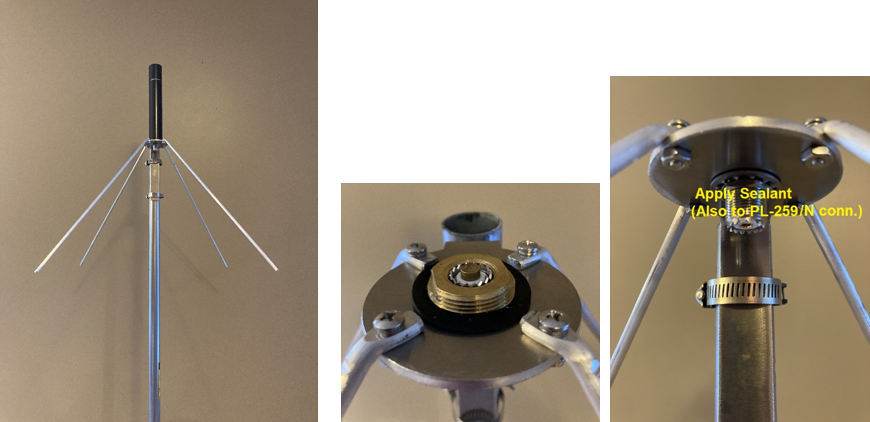
Easy installation; much of unit is pre-assembled
18” elements to ~3” diameter plate attachment; elements optimally angled in factory at 45 degrees below the horizon
Plate has NMO mount above
Stainless steel hose clamps provided allow for 1 ¼ “ – 1 ¾ ” OD mast/pipe
Maximum Power Rating: 200 Watts up to 225 MHz, 100 Watts at higher frequencies
under normal use and conditions [Follow specifications of antenna used.]
Gain: Nominal 3(+) dBi / 3-5(+) dB-MEG with COMPACtenna Vehicle Antenna attached
Due to diverse EM Fields of the Magnetic Field Resonator, performance is greater than predicted
based on (singular polarization/peak gain) field-range/anechoic chamber gain studies alone,
in NLOS (Non-Line-Of-Sight) environments which is the world we live in.
(V)SWR: nominal <2:1, range 144 – 512 MHz for -SO239 model, 144-1000 MHz for -N model
Specific frequencies depending on vehicle antenna utilized
(V)SWR’s (and pattern) are affected by surrounding (metal) structures
(V)SWR’s seen by the radio are often lower due to coaxial/feed-line attenuation.
Always check SWR; operate only per transmitter/amplifier specifications.
To reduce parasitic interaction, min. recommended height above ground and distance from RF-interacting materials is 10’; performance often escalates substantially 30’ (+) above ground.
Each Antenna product is quality checked.
Keep antenna and mount contacts clean. Fine grit emery cloth, for example, may remove oxidation.
[Thread lengths and center contact heights of different NMO mounts vary; make certain of good contact by antenna leaf spring – at times pulling the antenna leaf spring downward slightly is helpful before screwing antenna onto mount, especially if changing to another mount. Removing, re-attaching antenna repeatedly is not recommended; dedicated vehicle & base station systems are best.]
Use lube provided for NMO threads, center contacts and gasket, hand tighten securely.
The antenna side screw is an added measure for secure physical integrity; it is to be left alone.
[Design and specifications subject to change without notice.]
QST (ARRL) August, 2022: COMPACtenna Model 2M/440+, mobile and on CompacCounterpoise
John & Eileen Whitesell of Oklahoma were using a J-Pole antenna on their porch, but had a high noise floor.
They switched to the COMPACtenna model 2M/440+ on CompacCounterpoise Ground Plane Radial Kit.
The unwanted RF noise went away, and they had much better desired signal even with forest penetration.
Reviews by DX Engineering customers utilizing the CompacCounterpoise:

Base Station COMPACtenna on CompacCounterpoise DEMO by Eric Hofer, KJ4YZI – Ham Radio Concepts YouTube Link
***
See ‘INSTALLS’ page.
***
Available at:
Link to model CompacCounterpoise at DX Engineering
Link to model CompacCounterpoise-N at DX Engineering
Link to model CompacCounterpoise at Ham Radio Outlet
Link to model CompacCounterpoise-N at Ham Radio Outlet
Model 2M/440+
All the high performance of the 7.5” model 2M/440, PLUS an additional 1.5dB of gain,
and greater power handling capacity.
It is for those where 9″ is allowable/desirable and the operator wants that extra ‘edge’.
Ham Radio 2-Meter + 440 Bands for NMO mounts
Broad elevation coordinate signal pattern and elliptical polarization of COMPACtenna provides stabilized signals in our common Non Line of Sight environments,
with temperature and humidity inversion pathways as well as tropospheric propagation, and satellite communications.
Product Name: COMPACtenna MADE IN THE USA Model: 2M/440+ 9”
Optimized Compact High Performance HAM Radio Antenna for 2 Meter + 440 Bands
The 2M/440+ : All the high performance of the 7.5” model 2M/440, PLUS an additional ~1.5dB of gain, and greater power handling capacity. Designed for those where this ~ 9″ long x 1.5” dia. model is allowable/desirable and the operator wants that extra ‘edge’.
Reliable leaf spring style NMO connector on antenna for standard center-stud style NMO mounts
Antenna Type: Unique Electric/Magnetic Field Diversity Science & Technology Patented Design Patent No. US 9,407,001
With a special design construct of spiraled and cylindrical metal sheeting including ‘extended flat monofilar spiral Tesla-like coils’,
all resistance, inductance and capacitance (matching) is efficiently done by the physical metallic geometric form of the antenna itself,
as opposed to internal or external (lossy) components of other designs.
“Magnetic Field Resonator”: This built-in resonating matching system is an effectual component of the electromagnetic E & H fields production, resulting in better performance than expected for such a small antenna.
With a particularly strong magnetic near field, proximity noise is reduced.
And resulting diverse effective electromagnetic fields (elliptical polarization and phase diversity) as well as broad elevation coordinate signal pattern provides stabilized signals in our common Non-Line of Sight environments, with temperature and humidity inversion pathways & tropospheric propagation, and satellite communications, further enhancing performance in our world of (dynamic) obstructions, mitigating signal drops, reducing flutter, and increasing reliable range.
Each antenna manufactured is precisely tested/tuned before shipment.
System Applications:
Digital & Analog VHF Amateur (HAM) Radio
Digital & Analog UHF Amateur (HAM) Radio
Broad elevation coordinate signal pattern and elliptical polarization of COMPACtenna provides stabilized signals
in our common Non Line of Sight environments, with temperature and humidity inversion pathways
as well as tropospheric propagation, and SATELLITE communications.
Maximum Power Rating: 100 Watts 2 Meter Band; 75 Watts 440 Band
At maximum power, duty cycle is 50%: Up to 1 minute transmit in any 2-minute period
Under normal use and conditions
With longer transmissions, higher duty cycles, incl. with such as digital communications, decrease power, provide ‘cooling-off’ periods.
Gain: Nominal 5(+) dB-MEG
Due to diverse EM Fields of the Magnetic Field Resonator, performance is greater than predicted
based on (singular polarization/peak gain) field-range/anechoic chamber gain studies alone,
in NLOS (Non-Line-Of-Sight) environments which is the world we live in.
(V)SWR: Nominal < 2:1 144-148 MHz; 430-450 MHz
Best (V)SWR’s especially on VHF frequencies are generally seen when mounting at upper corners of a vehicle.
Signal pattern is substantially omnidirectional at corner locations, utilizing the downward/sloping metal of vehicle as counterpoise
METAL Ground Plane Vehicle Counterpoise – Apply antenna mount to metal with good (clean) ground connection;
Magnet mount type provides capacitive coupling, the ‘Flat’ style often provides best SWR’s
Mount types: see INSTALLS page
(V)SWR’s can vary with size & shape of vehicle & accessories; (V)SWR’s seen by the radio are often lower due to feed-line attenuation.
Always check SWR; operate only per transmitter/amplifier specifications.
Base Station antenna
This revolutionary antenna may also be used as a high performance compact base station antenna
by utilizing the COMPACtenna CompacCounterpoise, a heavy duty ground plane counterpoise radial kit
optimized for gain, pattern and SWR on VHF and UHF frequencies. To reduce parasitic interaction, min. recommended height above ground and distance from RF-interacting materials is 10’; performance often escalates substantially 30’ (+) above ground.
Each Antenna is quality checked and tuned. Keep antenna and mount contacts clean. Fine grit emery cloth, for example, may remove oxidation. Thread lengths and center contact heights of different NMO mounts vary; make certain of good contact by antenna leaf spring – at times pulling the antenna leaf spring downward slightly is helpful before screwing antenna onto mount, especially if changing to another mount. Removing, re-attaching antenna repeatedly is not recommended; dedicated vehicle & base station systems are best. Use lube provided for NMO threads, center contacts and gasket, hand tighten securely. Brushless car washes, hand washing reduce risk of antenna/mounting damage. The antenna side screw is an added measure for secure physical integrity; it is to be left alone.
[Design and specifications subject to change without notice.]
Reduced Flutter and Increased Reliable Range in the Dynamic Obstructed Multi-Path NLOS (Non Line Of Sight) Environment we live in is made possible
by the Diverse Electromagnetic Fields of The Magnetic Field Resonator constructed of ‘extended flat monofilar spiral Tesla-like coils’ + geometric components.
This New Science & Technology 9″ Model can ALSO Dominate Performance of much longer standard antenna technology in Long Range LOS – Line of Sight Communications!
from eHam.net:

Talking THROUGH DIRT – by Dr. Marc (NM0D), Rosemary (KE5CMS) & Brett (KI5TAX)


Base Station COMPACtenna MODEL 2M/440+ on CompacCounterpoise DEMO by Eric Hofer, KJ4YZI – Ham Radio Concepts YouTube Link
***
Mobile: For best SWR and performance, mount your COMPACtenna
at/near an upper corner of your vehicle.
See top of this Home Page and ‘INSTALLS’ page.
***
Available at:
Link to COMPACtenna model 2M/440+ at DX Engineering
Link to COMPACtenna model 2M/440+ at Ham Radio Outlet
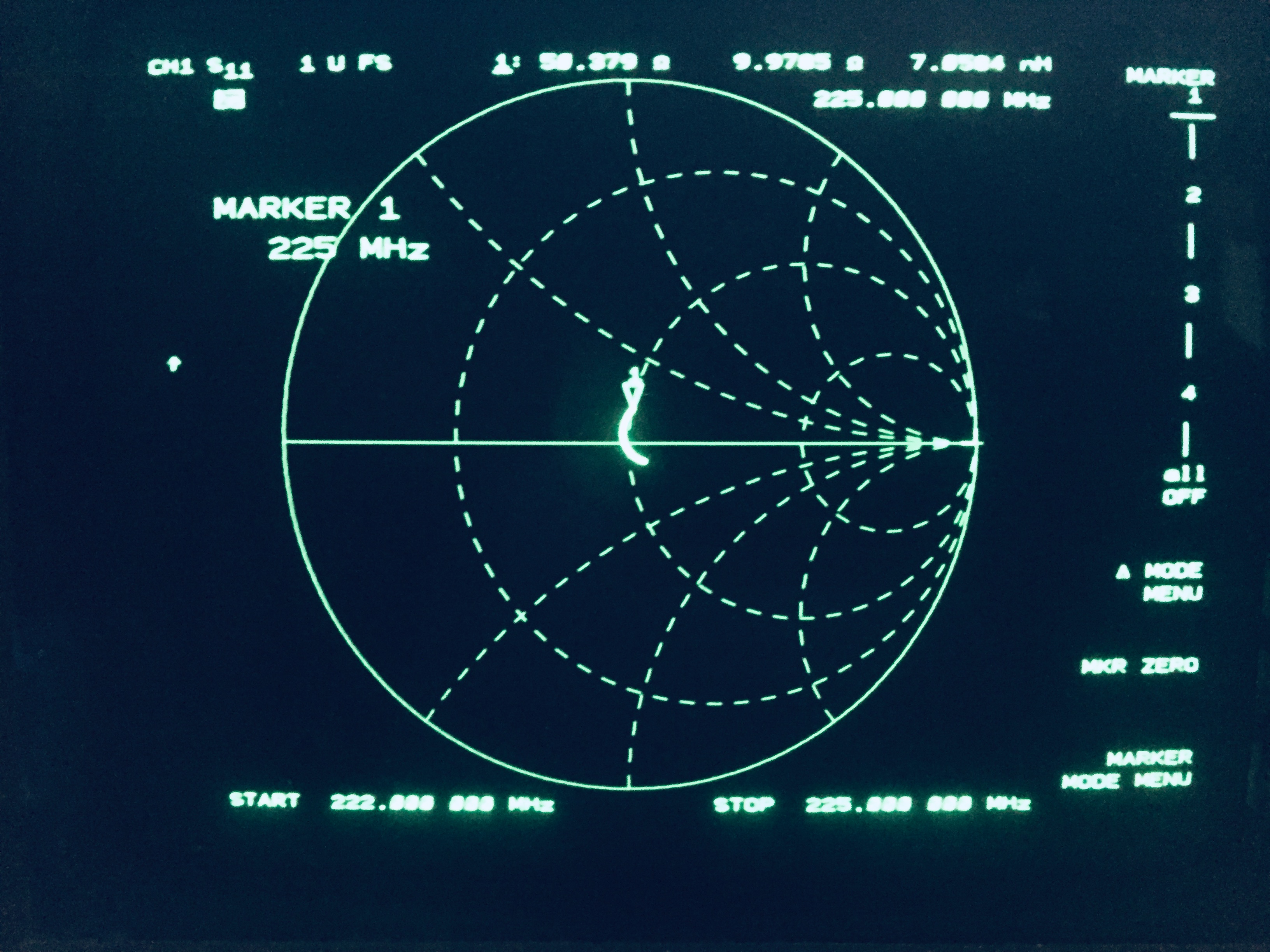
Model 220MAX Ultimate 220MHz Antenna

Product Name: COMPACtenna MADE IN THE USA Model: 220 MAX 9”
Optimized Compact High Performance HAM Radio Antenna for the 220MHz (1.25m) Band
The 220 MAX : Maximum Gain, Higher Power Handling, Low SWR
Designed for those where this ~ 9″ long x 1.5” dia. model is allowable/desirable and the operator wants that extra ‘edge’.
Reliable leaf spring style NMO connector on antenna for standard center-stud style NMO mounts
Antenna Type: Unique Electric/Magnetic Field Diversity Science & Technology Patented Design Patent No. US 9,407,001
With a special design construct of spiraled and cylindrical metal sheeting including ‘extended flat monofilar spiral Tesla-like coils’,
all resistance, inductance and capacitance (matching) is efficiently done by the physical metallic geometric form of the antenna itself,
as opposed to internal or external (lossy) components of other designs.
“Magnetic Field Resonator”: This built-in resonating matching system is an effectual component of the electromagnetic E & H fields production, resulting in better performance than expected for such a small antenna.
With a particularly strong magnetic near field, proximity noise is reduced.
And resulting diverse effective electromagnetic fields (elliptical polarization and phase diversity) as well as broad elevation coordinate signal pattern provides stabilized signals in our common Non-Line of Sight environments, with temperature and humidity inversion pathways & tropospheric propagation, and satellite communications, further enhancing performance
in our world of (dynamic) obstructions, mitigating signal drops, reducing flutter, and increasing reliable range.
Each antenna manufactured is precisely tested/tuned before shipment.
System Applications:
Digital & Analog Amateur (HAM) Radio
Broad elevation coordinate signal pattern and elliptical polarization of COMPACtenna provides stabilized signals
in our common Non Line of Sight environments, with temperature and humidity inversion pathways
as well as tropospheric propagation, and SATELLITE communications.
Maximum Power Rating: 65 Watts
At maximum power, duty cycle is 50%: Up to 1 minute transmit in any 2-minute period
Under normal use and conditions
With longer transmissions, higher duty cycles, incl. with such as digital communications, decrease power, provide ‘cooling-off’ periods.
Gain: Nominal 5(+) dB-MEG
Due to diverse EM Fields of the Magnetic Field Resonator, performance is greater than predicted
based on (singular polarization/peak gain) field-range/anechoic chamber gain studies alone,
in NLOS (Non-Line-Of-Sight) environments which is the world we live in.
(V)SWR: Nominal < 2:1 222-225 MHz
Best (V)SWR’s especially on VHF frequencies are generally seen when mounting at upper corners of a vehicle.
Signal pattern is substantially omnidirectional at corner locations, utilizing the downward/sloping metal of vehicle as counterpoise
METAL Ground Plane Vehicle Counterpoise – Apply antenna mount to metal with good (clean) ground connection;
Magnet mount type provides capacitive coupling, the ‘Flat’ style often provides best SWR’s
Mount types: see INSTALLS page
(V)SWR’s can vary with size & shape of vehicle & accessories; (V)SWR’s seen by the radio are often lower due to feed-line attenuation.
Always check SWR; operate only per transmitter/amplifier specifications.
Base Station antenna
This revolutionary antenna may also be used as a high performance compact base station antenna
by utilizing the COMPACtenna CompacCounterpoise, a heavy duty ground plane counterpoise radial kit
optimized for gain, pattern and SWR on VHF and UHF frequencies. To reduce parasitic interaction, min. recommended height above ground and distance from RF-interacting materials is 10’; performance often escalates substantially 30’ (+) above ground.
Each Antenna is quality checked and tuned. Keep antenna and mount contacts clean. Fine grit emery cloth, for example, may remove oxidation. Thread lengths and center contact heights of different NMO mounts vary; make certain of good contact by antenna leaf spring – at times pulling the antenna leaf spring downward slightly is helpful before screwing antenna onto mount, especially if changing to another mount. Removing, re-attaching antenna repeatedly is not recommended; dedicated vehicle & base station systems are best. Use lube provided for NMO threads, center contacts and gasket, hand tighten securely. Brushless car washes, hand washing reduce risk of antenna/mounting damage. The antenna side screw is an added measure for secure physical integrity; it is to be left alone.
[Design and specifications subject to change without notice.]
***
Mobile: For best SWR and performance, mount your COMPACtenna
at/near an upper corner of your vehicle.
See top of this Home Page and ‘INSTALLS’ page.
***
Available at:
Link to COMPACtenna model 220 MAX at DX Engineering
Link to COMPACtenna model 220 MAX at Ham Radio Outlet
Model 20/40Micro tiny antenna for the 20 & 40 Meter HF Bands
“REVOLUTIONARY !”
HF ‘Plug-and-Play’ Connect to your radio/coaxial lead & operate in seconds

Antenna has an incorporated 5’ quality flexible UV-resistant coaxial cable terminated with select ferrite beads and a PL-259.
An SO-239 double female barrel adapter is included for connecting a PL-259 terminated extension cable.
HOA, Home, Condo
Better performance is generally seen with antenna one or two floors above ground level such as in an attic or closet
and about 10 feet or more from metal/RF-interactive structures.
If your home has undesirably high RF noise (such as from electrical appliances, switching power supplies of electric devices,
even light bulbs, etc.) that you aren’t able to reduce sufficiently with such as grounding, ferrite beads, antenna location, etc.
(see INSTALLS page of COMPACtenna.com for helpful ideas),
or your home is made of RF absorbing/reflective/interactive material (walls/roof),
consider placing the antenna outside.
All materials and construct are weather/UV resistant.
Consider placing the antenna on/in a wooden, fiberglass or PVC, other non-RF Interacting material structure
such as an archway-arbor-trellis, shed/barn, gazebo, pergola, patio roof, patio over-head structure,
or even (temporary, as appropriate) a fiberglass ~10’ step-ladder.
If needed, 2 lip thru-holes near the top of the antenna may be used to secure its position, such as with black (UV stable) plastic wire ties.
Better performance is generally seen with antenna about 10 or more feet above ground/water
and about 10 or more feet from metal/RF-interactive structures
Only 10” x 10” x 10” (only 2.5 pounds)
No ground plane counterpoise needed, No ground stake needed, No metal mast needed (do not use – see above), No wires needed
Each antenna manufactured is precisely tested/tuned before shipment.
Low SWR: nominal <2:1
The entire 20 Meter Band 14-14.35 MHz
On the 40 Meter Band 7.1-7.2 MHz; much of/entire band with tuner
With internal tuners choose center frequency with SWR<3:1 and then activate internal tuner
Proximity to metal/RF-interactive structures/materials can affect SWR
Maximum Power Rating: 100 Watts SSB voice; 15 Watts other modes
Under normal use and conditions
Always check SWR; operate only per transmitter/amplifier specifications
Antenna Type: Unique Electric/Magnetic Field Diversity Science & Technology Patented Design Patent No. US 9,407,001
Special design construct of spiraled metal sheeting including ‘extended flat monofilar spiral Tesla-like coils’
“Magnetic Field Resonator”: This built-in resonating matching system is an effectual component of the electromagnetic E & H fields
production, resulting in better performance than expected for such a small antenna.
Antenna is omni-directional (works in all directions)
Ionosphere propagation including NVIS
is supported by broad hemispheric elevation coordinate pattern, phase delay, and elliptical polarization.
With a particularly strong magnetic near field, proximity noise is reduced.
Follow applicable RF-Exposure Regulations.
Follow local building codes including NEC grounding/lightning/etc. and NFPA guidelines.
Don’t touch any part of antenna structure, support, feedline, grounding,
lightning arrestor components/systems nor any other part of installation and related parts/structures while transmitting.
[Design and specifications subject to change without notice.]

